
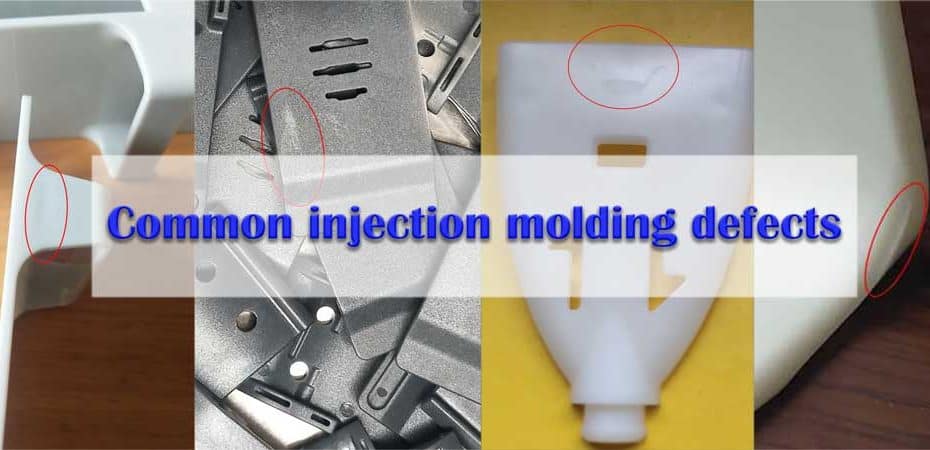
When it comes to injection molding, the chances you might end up making a costly mistake is too high. Quality concerns in injection-molded materials can vary from small surface defects to more severe defects that can influence the product’s durability, efficiency, and functionality.
Concerns associated with the molding process, including the use of materials, the nature of tools, or a mixture of all three may trigger them. But learning how molding defects occur, just like other consistency concerns, is only a small part of the fight against quality concerns. Any understanding of typical molding flaws and how to prevent them will assist you in minimizing costs related to unsold products and inventory levels as an importer or producer of injection-molded materials.
The following are the most popular injection molding-related quality defects, what induces them, and what you can try to avoid them.
MOLDING DEFECTS ARE MOST FREQUENTLY CAUSED BY PROCESS-RELATED INADEQUCIES
It could be complicated or pricey to fix certain molding defects. Rest can be avoided without a need to modify the mold tools and equipment or substitute other manufacturing equipment by changing the molding process. Frequently, you can quite effectively prevent these defects by merely changing the mold’s flow rate, temperature, or pressure.
Flow Lines
Flow lines surface as a wavy pattern of a subtly different color than that of the background field and on smaller areas of the molded portion also. They could also occur on the surface of a component close to the mold entry points, or “gates” that the molten content flows into, as ring-shaped bands. Usually, flow marks probably won’t affect the integrity of the piece. Although when used in certain consumer products, like high-end goggles, they could be unflattering and might even be inappropriate.
The causes and solutions for flow lines
Flow lines are quite likely the outcome of changes in the substance’s cooling speed since it moves around the mold in multiple directions. Wall thickness variations may very well cause the material to settle at differing speeds, leaving flow lines behind. Molten plastic, for instance, cools fairly rapidly during the injection process, and where the injection speed becomes too sluggish, flow marks are visible. When already filling the mold, the plastic turns partly rigid and soggy, allowing the wave pattern to emerge.
When it comes to injection-molded products, here are several typical solutions for flow lines:
- To make sure the liquid reaches the mold fully before cooling, enhance the injection pace, pressure, and material temperature.
- Round the mold corners where wall thickness expands to aid and ensure a steady flow rate and avoid flow lines
- To help avoid material from cooling too early during flow, relocate mold gates to provide more space between them and the mold coolant.
- To improve flow velocity and avoid excessive cooling, increase the nozzle diameter
Taking Care of Burn Marks
Burn marks normally occur on the edges or surface of a molded plastic component as black or rust-colored decoloration. Injection molding defects. Burn marks usually do not impact product functionality until the plastic is burnt to the point of corrosion.
Causes and Prevention of Burn Marks
Trapped air, or the resin itself, overheating in the mold cavity during injection, is the normal source of burn marks in injection-molded sections. Extreme rates of injection or substance warming sometimes contribute to excessive heat that induces burns.
To resist burn marks in molded materials, take the following preventive measures:
- Stop heat stress, minimize the temperature of the melt and mold
- To reduce the risk of trapping air on the inside of the mold, reduce the injection velocity
- Increase the size of gas vents and gates to enable the mold to resist trapped air
- Reduce the mold cycle time so there can be no risk of overheating any trapped air and resin.
Warping
Warping is a deformation that can develop as various portions of a component compress irregularly in injection-molded products. Same as wood can distort as it dries inconsistently, as irregular shrinkage places excessive stress on various parts of the molded component; plastic and other materials can deform during the cooling process. Bending or turning of the completed component as it cools is a result of this undue tension.
I used to take Xanax for insomnia, but when I decided to step off the treatment, I faced severe problems related to withdrawal. My psychiatrist recommended switching to Valium. It has a longer half-life and can help me go through withdrawal easier. I’ve been on Valium for three weeks. Now I’m off, and everything’s fine.
Causes and Prevention of Warping in Molded Parts
An injection-molded plastic and related materials, several of the key reasons for warping are that cooling occurs too fast. The issue can indeed be exacerbated by high temperatures or poor thermal conductivity of the molten material.
In other instances, where the walls of the mold are not of uniform thickness, mold construction will lead to warping. Shrinkage increases with wall thickness. In your molded bits, here are some common ways to avoid warping:
- Ensure that the cooling process is slow and lengthy enough to reduce uneven material stresses
- Lower the substance or mold temperature
- Try converting to a substance that during cooling tends to shrinks less (e.g. particle-filled thermoplastics shrink much less than semi-crystalline materials or unfilled grades)
- To ensure greater stability in the component during cooling, redesign the mold with uniform wall thickness and part symmetry
Vacuum Voids
Vacuum voids are stuck air bubbles, or air pockets, that occur in a completed molded object. Specialists in quality management usually deem voids to be a “minor” flaw. Although in several situations, greater or more extensive voids can damage the molded component, since there is air underneath the surface of the part where the molded material ought to be.
Usual reasons and precautions for preventing vacuum voids in molded components:
Unsatisfactory molding pressure to drive compressed air out of the mold cavity is indeed one of the main causes of voids. In most instances, the layer nearest to the mold wall cools too fast, allowing the material to harden and force the material around the outside, forming an abscess.
If its density varies dramatically from the liquid to the hardened state, the substance itself can be highly prone to voids. In shaped sections that are thicker than 6 mm, voids are more difficult to prevent.
Successful methods of avoiding voids include:
- To push out compressed air pockets by raising the injection pressure
- Pick a good lower-viscosity grade of substance to reduce the chance of air bubbles developing
- To avoid excessive cooling where the substance is most prone to voids, position gates near to the thickest areas of the mold.
Sink Marks
Sink marks can be defined as tiny holes or depressions on top of a smooth and even surface of a molded part. these are usually caused when the internal part of a molded component shrinks and pulls some of the material on the external side towards the inside.
Reasons for Sink Marks and How you can Prevent them
Sink marks are comparable to vacuum voids, except in cause and effect, they are opposite. The material on the inside cools excessively slow rather than the material cooling too quickly near the outside of the component. Before it can cool sufficiently, the resultant compression forces the outer material inside, resulting in depression. However, with voids sink marks are more prone to occur in thicker sections of the component. To avoid this flaw, here are several actions you can take:
- Increase the keeping pressure and duration to enable cooling of the substance towards the surface of the component
- Increase the time of cooling to reduce shrinkage
- To allow faster cooling near the top, build your mold with thinner part walls.
Weld Lines
Weld lines may occur on a molded part’s surface where, after breaking off into two or more directions in a mold, the molten material has converged. The hair-like weld line is the product of poor binding of materials, which reduces the part’s durability.
Popular reasons and how to stop welding lines:
When colliding, two or more facets of polymer or other molten substance need to preserve a certain temperature. Alternatively, they become partly solidified and will not bind adequately where they cross, leading to welding lines. In-molded parts, typical treatments for welding lines include:
- Rising the temperature of the substance to stop partial solidification
- Increase the injection speed and pressure until the substance has filled the mold to restrict cooling.
- To remove partitions, rebuild the mold to
- To allow quicker flow and avoid early cooling, move to a substance with a lower melting temperature or viscosity.
Jetting
- Jetting amounts to some kind of deformation in a molded object that can arise as the mold cavity is infused with an initial “jet” of liquid content that tends to solidify until the cavity it is filled with. The Jetting also occurs on the surface of the completed part as a squiggly line, usually leading from the primary injection gate. This noticeable pattern of flow may result in a deficiency of the component. Excessive injection pressure is the primary cause of jetting. As molten polymer or other substance is pumped through a narrow gate at high pressure, it frequently squirts via the gate instantly, instead of steadily filling the mold cavity.
- Decreasing injection pressure to keep the substance from being easily squirted into the mold cavity
- Raising the sample and mold temperature to avoid early solidification of the initial jet of material
- The mold is constructed with the injection gate placed such that the liquid is guided through the mold rather than longitudinally.
DEFECTS COMMONLY ASSOCIATED WITH MATERIAL USE OR STORAGE
Defects in injection molding will also arise from the material itself as well as how the material is stored and treated by the producer before the manufacturing process. These defects can vary from slight cosmetic problems to the finished component’s compromised ability. Depending on the planned implementation of this, severe safety issues may also occur.
Discoloration
Where a molded component is a different shade than expected, discoloration, or “color streaking” happens. Sometimes, the decoloration on a molded component is confined to a small spot or a handful of stripes of irregular pigment. The visibility of the component is usually influenced by this defect without reducing its intensity.
Causes of discoloration and how to avoid it in molded goods
Possible factors are low thermal stability of the coloring agent or excessive masterbatch blending. To minimize the chance of discoloration in your injection-molded products, take the following precautions:
- Ensure the workers during manufacturing thoroughly cleans the hopper, nozzle, and mold to remove any remaining pellets or base content.
- To extract unwanted color from the unit, try using a purging compound to guarantee that a paint agent with sufficient thermal consistency is used by you or your supplier.
- For consistent color production, assure that the masterbatch is mixed uniformly
Delamination
If you find that the thin layers easily break or peel off the underlying material on the surface of a molded component, you can see a molding defect called delamination. Delamination, equivalent to what you will usually see on flake mica, is a defect marked by a flaking surface layer. In general, this is considered a reasonably significant defect since it decreases the component’s power.
Causes and Solutions to Delamination Injection Molding
Contamination of the resin pellets or another base substance with foreign material is the most common source of delamination. The effect of flaky separation is where the two materials do not bind together with each other.
For instance, a typical base plastic such as acrylonitrile butadiene styrene (ABS) may be mixed with an incompatible plastic such as polypropylene (PP). If the component is intended for a safety-critical use, the resultant lack of strength of the material will be very unsafe.
Aside from material fed into the hopper, any excess release agents coating the mold for easier separation of components could also be the contaminant. Moisture content on the material may also induce delamination, due to insufficient drying after use. If you detect delamination impacting your molded pieces, take the following corrective steps to avoid reoccurrence:
- If excess moisture is a concern, increase the mold temperature or pre-dry the material correctly.
- Ensure that the resin pellets or base material are correctly processed and treated by staff to avoid pollution.
- Take into account redesigning the mold to minimize the reliance on release agents by relying on the injection nozzle.
INJECTION MOLDING DEFECTS CAUSED BY POOR MOLD DESIGN OR MAINTENANCE
Defects may be inserted by complications with the mold tooling itself into molded products. There are likely to be such flaws where the mold is improperly handled or built. Especially in the above situation, where it is important to fully overhaul the mold. These defects may be hard or expensive to fix in future production runs.
Short Shot
A short shot happens where the flow of molten fluid does not occupy the cavities in a mold properly. The effect is that, after cooling, the molded part is incomplete. For example, the short shot may appear as incomplete compartments in a display’s plastic shelves or missing prongs on a plastic fork. Typically, short shots are categorized as a severe defect that may inhibit function or presentation.
Causes and Remedies of a Short Shot in Molded Products
Flow constraints arising from small or blocked gates are the most frequent source of short shots. The liquid is often too viscous or the mold is too cool to enable the molten material to cover the mold sufficiently before cooling. As well as other occasions, stuck air pockets may impede proper flow or it may be insufficient to inject pressure. To avoid short shots, take the following steps:
- Redesign the mold for improved flow with larger channels or gates
- Raise the speed or pressure of the injection or choose a thin base material to boost the flow
- To prevent material from cooling too fast, raise the temperature of the mold
- To allow trapped air to escape, install additional air vents or expand existing vents in the mold
Flash
Flash, sometimes called “spew” or “burrs”, is an overflow of molding material that occurs at the surface of a part as a thin lip or deformity. When fluid has circulated beyond the designed flow channels and into the gap between the tooling plates or at the injection pin, a ‘Flash’ occurs. The procedure for overhauling a flash molded component also entails snipping the excess content.
Common causes of flash and prevention in molded products
The most popular cause to flash a poorly-design or worn and degraded mold. The flash may also caused by extremely high mold temperatures or injection pressure. Matter streaming through the cavities of the mold will push its way among plates where there is insufficient plate clamping force. In-molded goods, popular methods for addressing flash include:
- If plates do not fit together properly or allow material to move outside the tube, retool or redesign the mold.
- Growing the clamping force of the plate to restrict the flow of material to the channel
- To enhance material flow, change the mold temperature, injection pressure, and ventilation
Conclusion
Usually, manufacturing with injection molding requires a considerable initial investment in tooling. And this is why building the mold correctly for the very first time is extremely valuable, rather than trying to start anew after discovering significant defects. Deformities related to the method or substance of molding tend to be simpler to solve and less expensive. However, no matter what the cause, the simple truth is that your brand can be affected greatly by flaws in your molded products.